It is so that I wanted to think a little about my own SV and the speedometer after so many built and built gear indicators V3 , but . It should come out no nonsense here and the criterion " fully integrated " and " no further controls " are met. Therefore, I have already finished the GA -V3 supplemented by another module . This is now in the gear indicator also a digital oil thermometer installed .
Since I also here before me the shortcomings of the accessories have looked at , I wanted to , though they know, have a reliable and above all accurate measurement. Therefore , I first searched for an optimal location. Solutions, such as screwed thermometer in place of the oil filler plug , drop out because of their random measurement method. In addition, in this technique, the measurement point is far too high. They are not surrounded by the oil. A modification of the oil drain plug would be conceivable , but it is not practicable . The drain plug is magnetic for good reason. You should hold loose metallic wear chips. It does not make sense to replace the magnet with a hole for a sensor therefore .
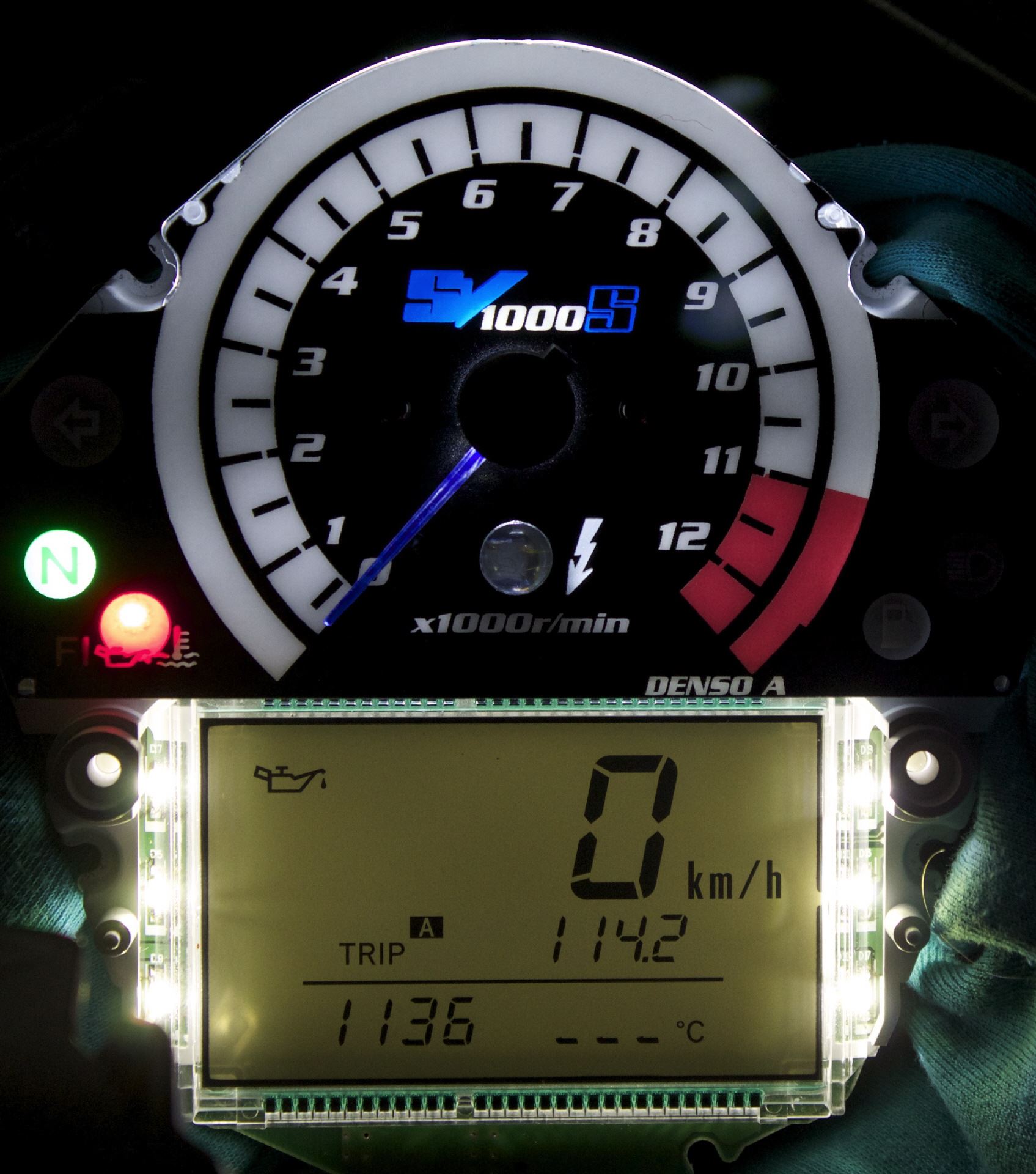
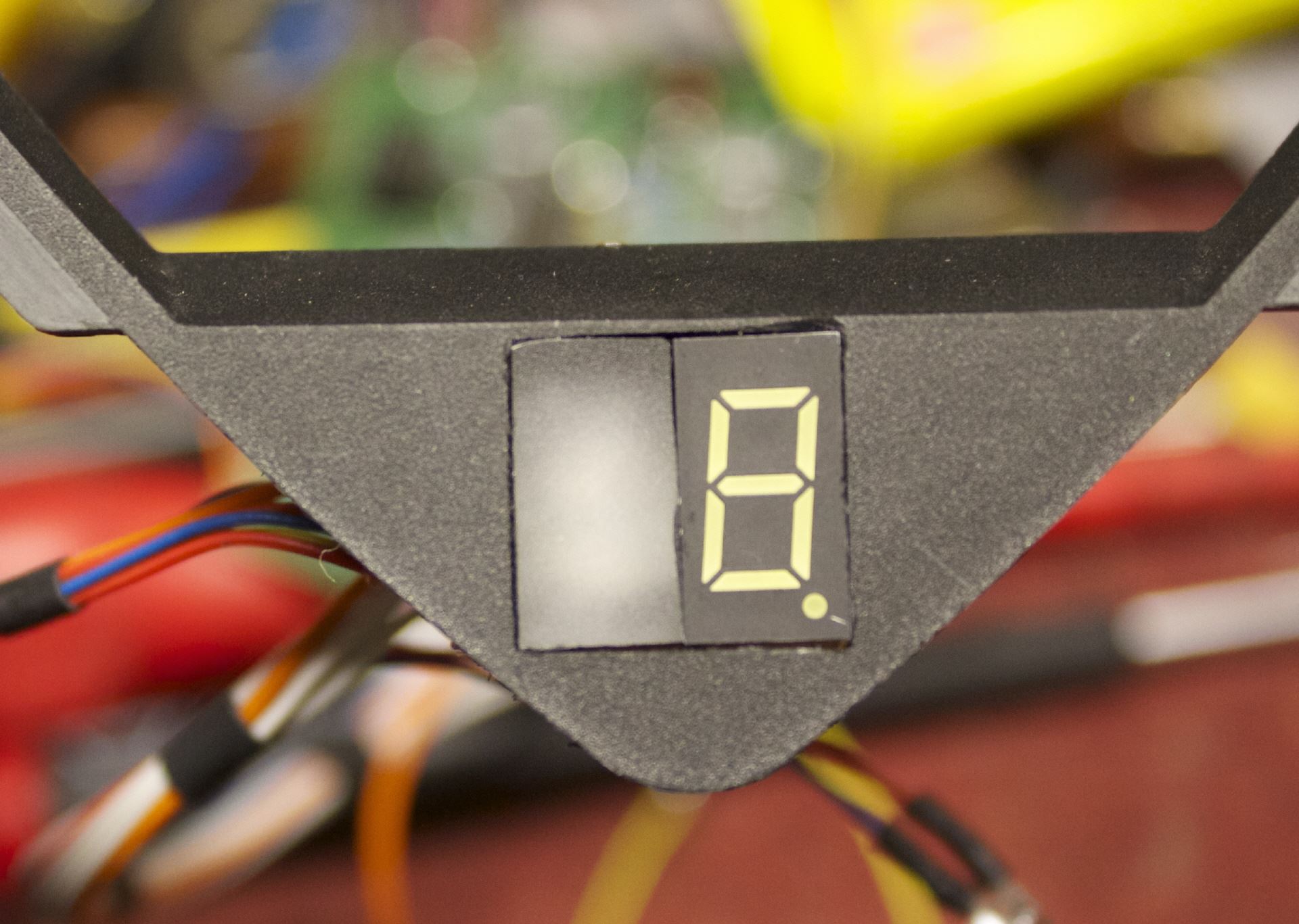
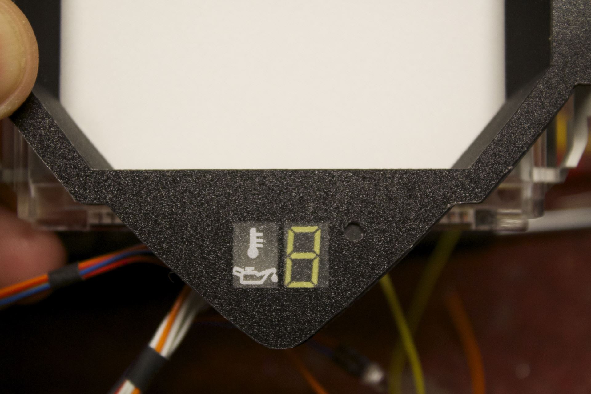
The implementation of the temperature measurement in the speedometer still required some thought exercises. The speedometer should be regarded as a unit as before. No external knobs, switches, etc. So really it should act as standard. Since the gear indicator is already taking the square below the triangle as an information center, so should no further numbers (temperature) move into the field of view. That would only lead to confusion or not immediate readability. I have therefore decided to use a simple symbolism.
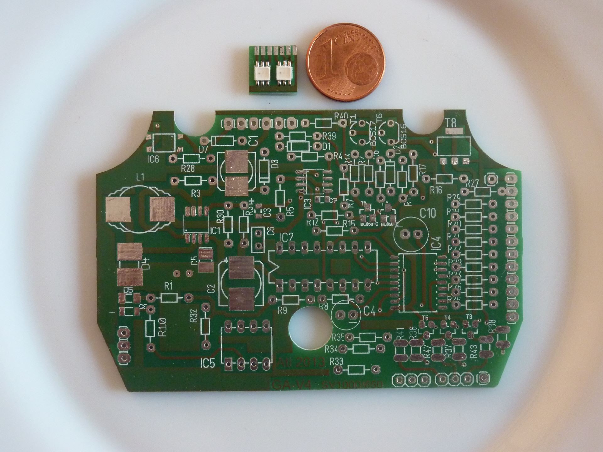
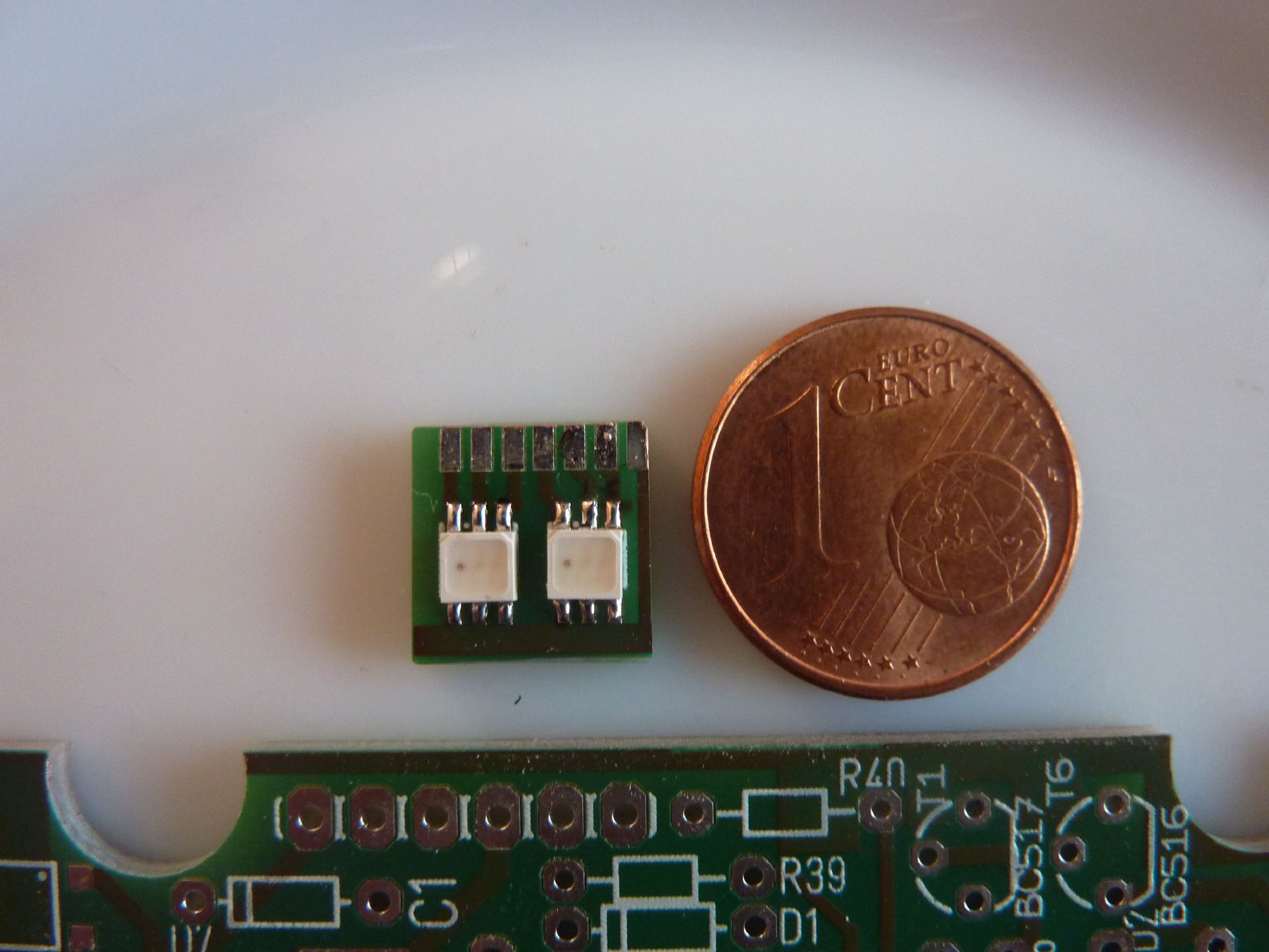
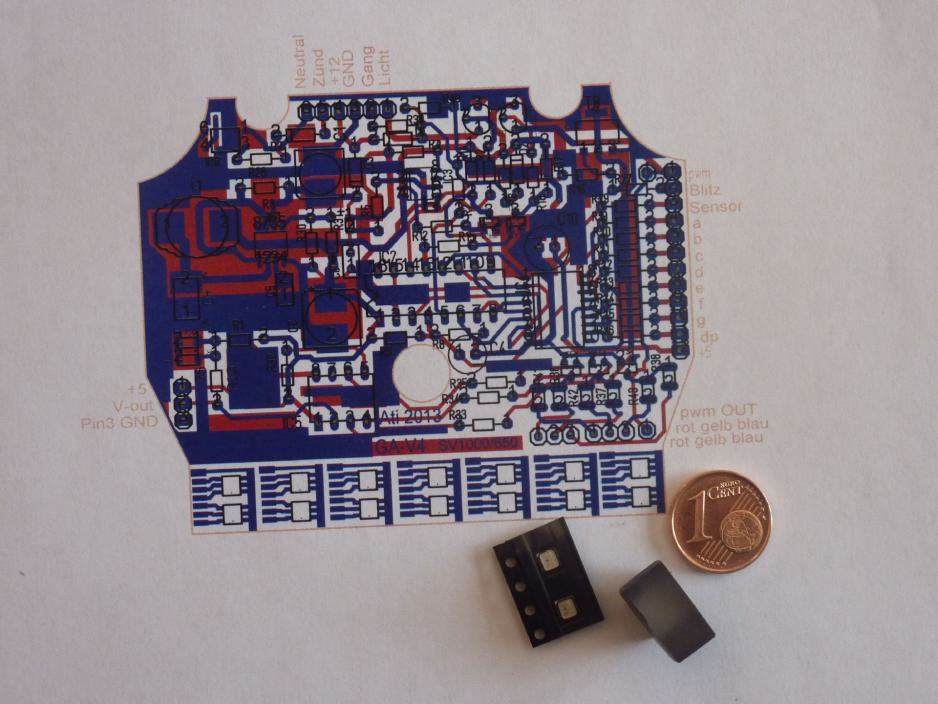
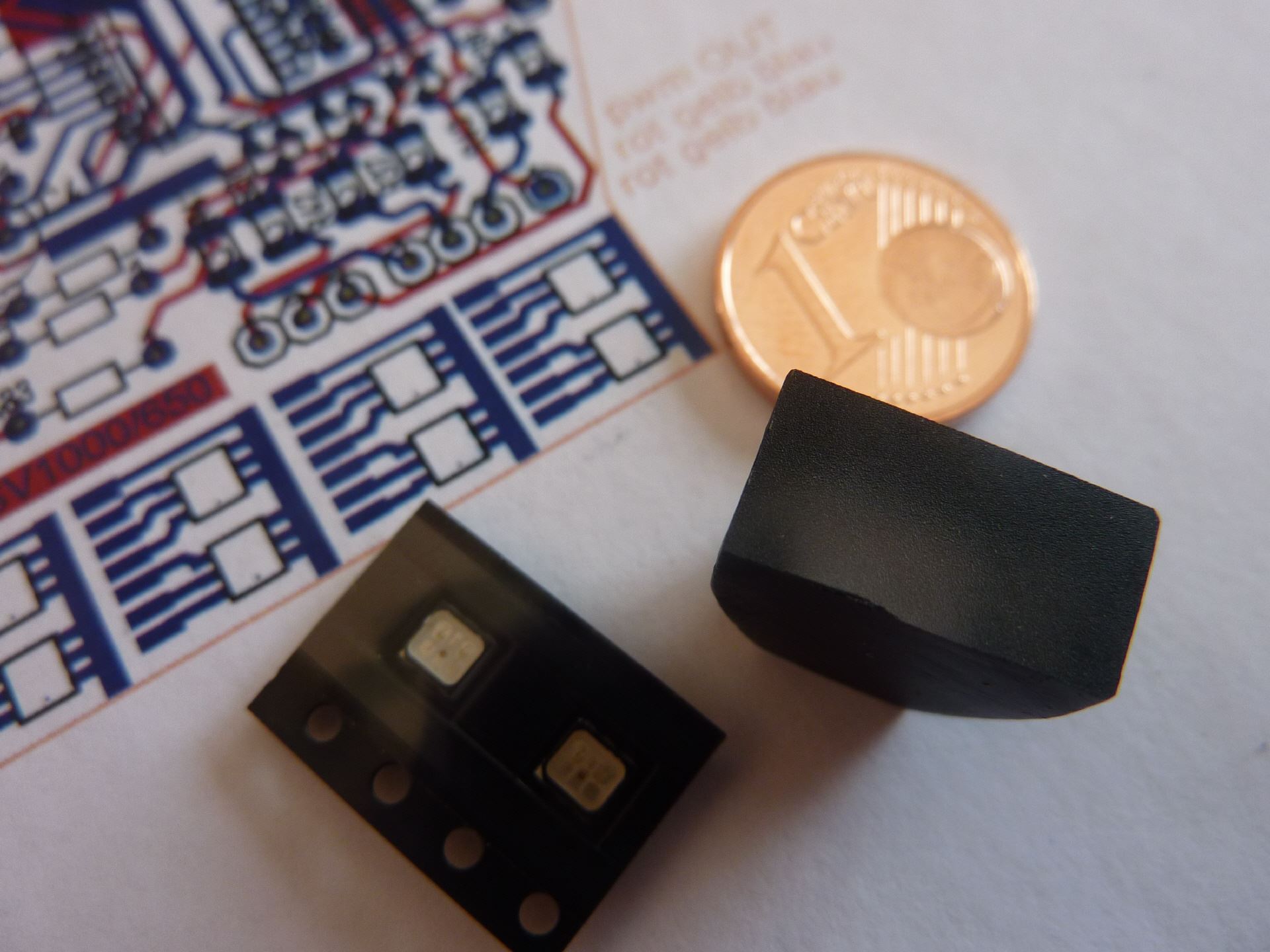
The symbol consists of a light window similar to the indicator lights for turn signals, idle, etc. with aufgerucktem icon. However, Beyond is an RGB LED unit that can indicate different states by different colors.
The gear indicator is based on the proven approach of the gear indicator V3. There is nothing to improve. However, addition is the little brother of the processor. He has the sole task of the temperature measurements. He signaled by a flashing blue a cold engine. This state goes to 45 C. Then the flashing turns into a steady blue lights. This is a turn up too cold engine when the rooster. At 70 C is solid green from the blue steady light. From here you can start. The oil is now sufficiently fluid to be pumped quickly and can reach all lubrication points.
This green status goes up to 130 C. Then the color changes and remain lit in red. This signals a high oil temperature, but is not yet alarming. From 140 C, the red goes to flashing red. This value is then already borderline for the oil. However, such temperatures may very well be achieved on the race track.
Also, this display is, like everyone else, controlled by the ambient brightness. Because the display is optimally adapted to gear display. The display window is placed with me next to the gear indicator. The symbols printed on should also be obvious other people. A symbolic thermometer and an oil can ensure this.
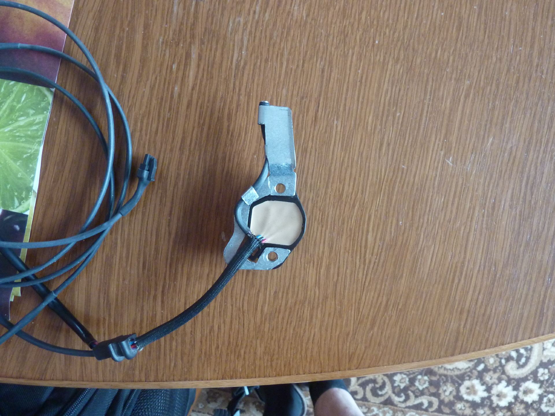
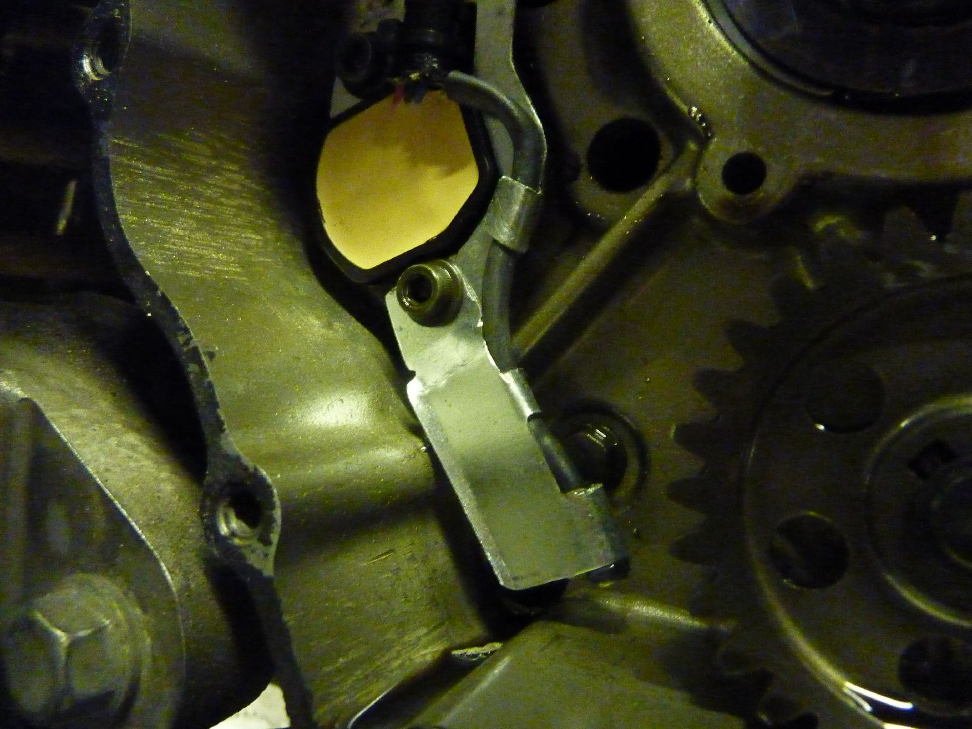
Clearly, this coupling must be removed. The gear sensor is yes, exactly behind it. Now the engine compartment but is filled with rotating gears , not to mention of the clutch pedal completely . So naturally an additional built-in part should be installed so sure that it does not come under extreme circumstances with rotating parts in contact . Therefore, I have stuck to the original mounting of the gear sensor. Since the temperature sensor weighs almost nothing , the holding part really only needs to support itself . The design can thus be made of lightweight material . I have decided for galvanized 0.5 mm steel sheet.
This sheet was cut out with a Dremel and tin snips . The contour is matched to the gear sensor . In addition, worked out flags form cable fixations for the lead . For the sensor itself is bent at the lower end of a sleeve which protrudes from the sensor head down . This also has nothing to swing with vibration begins the long side has an edge
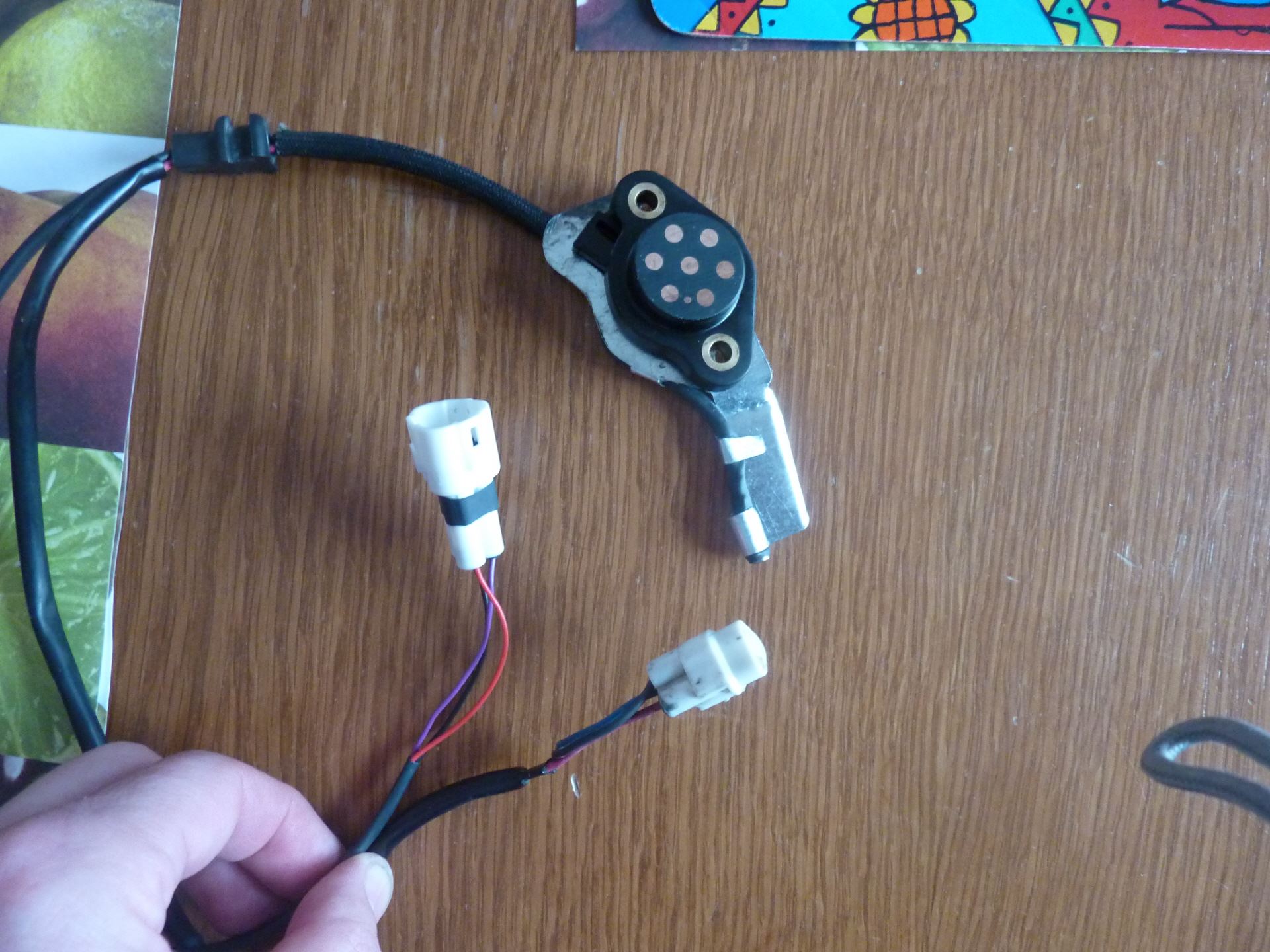
 Gangsensor mit Temperatursensor
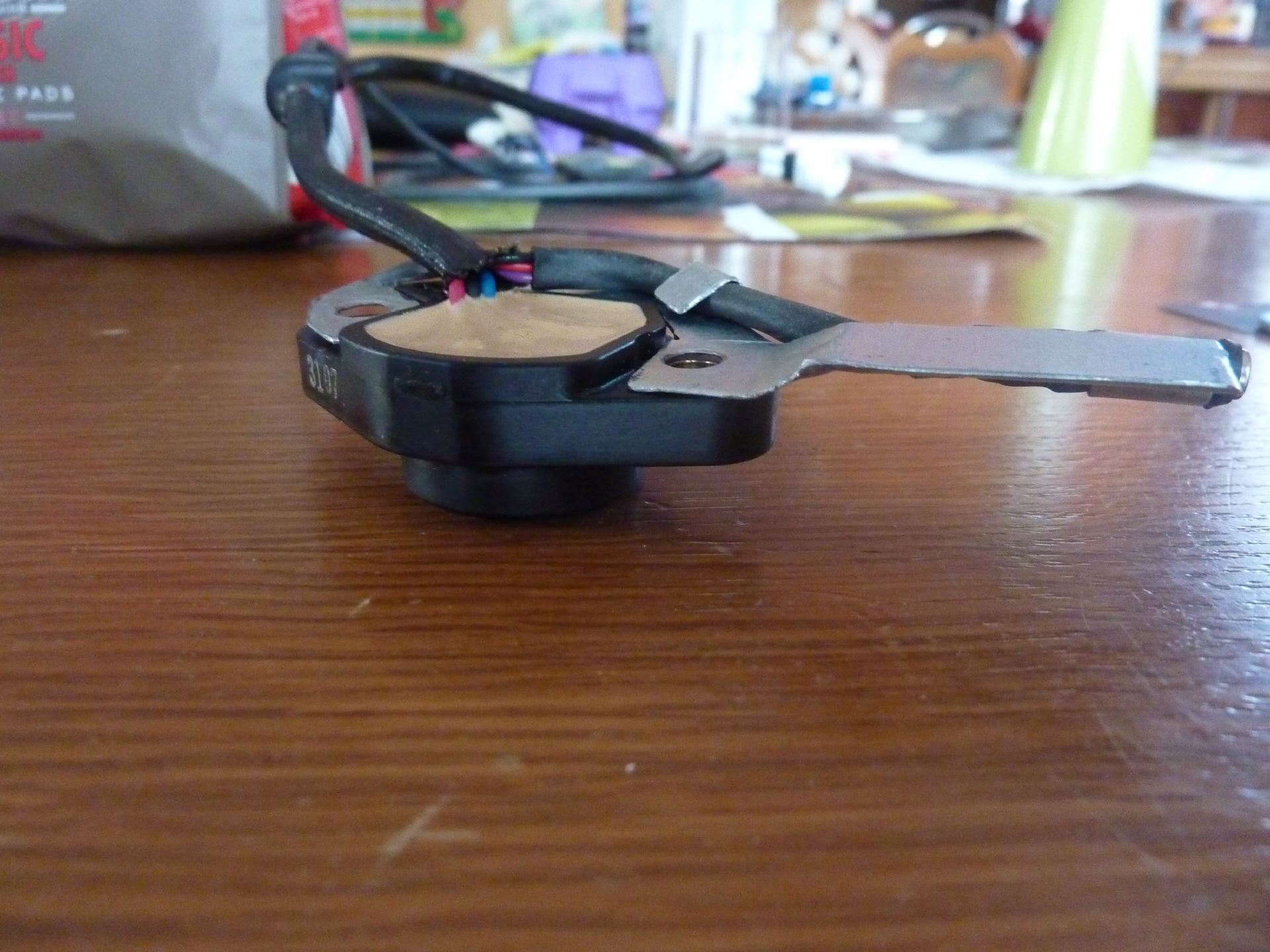
 Der Sensor
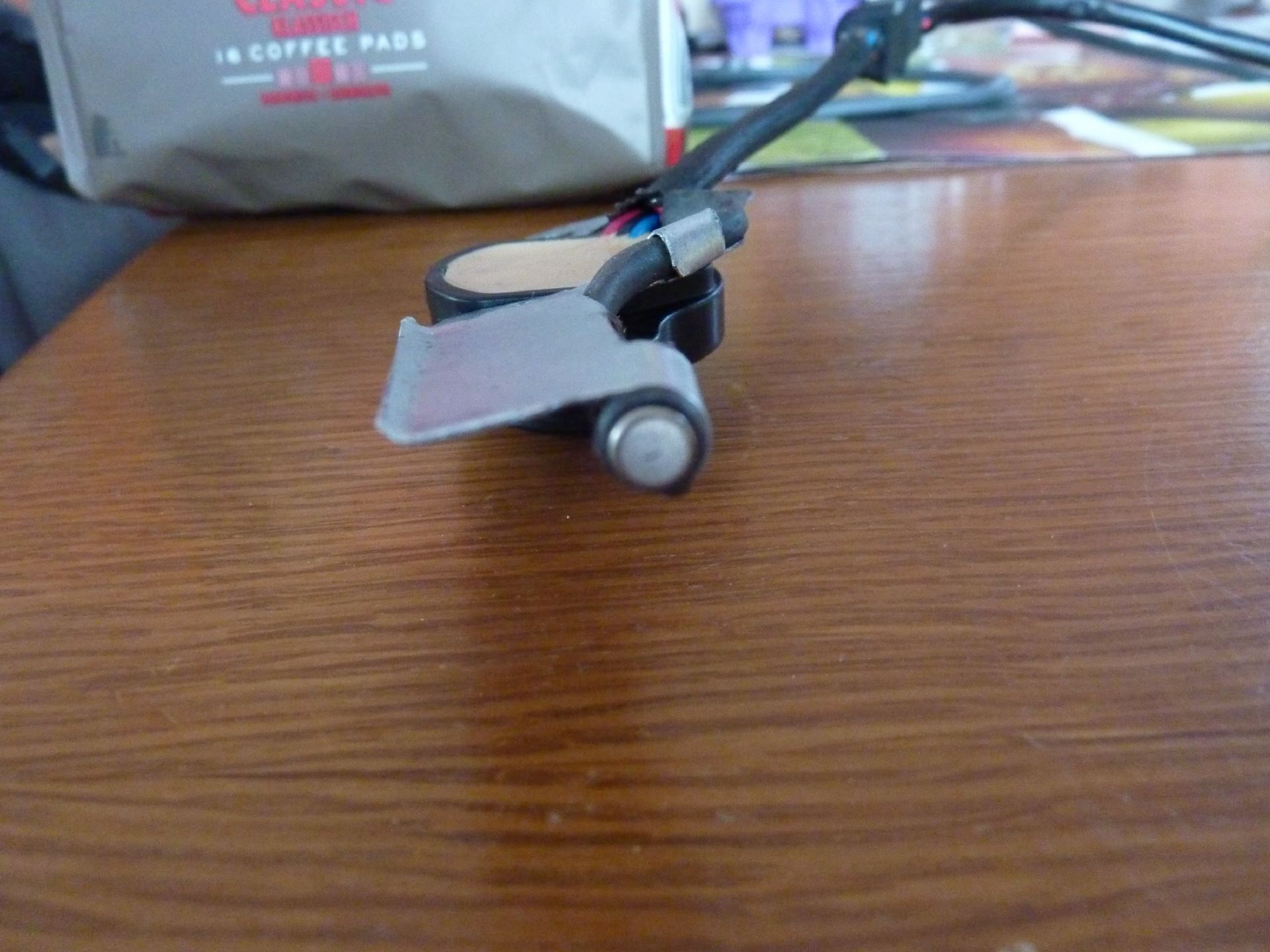
 eingebaut
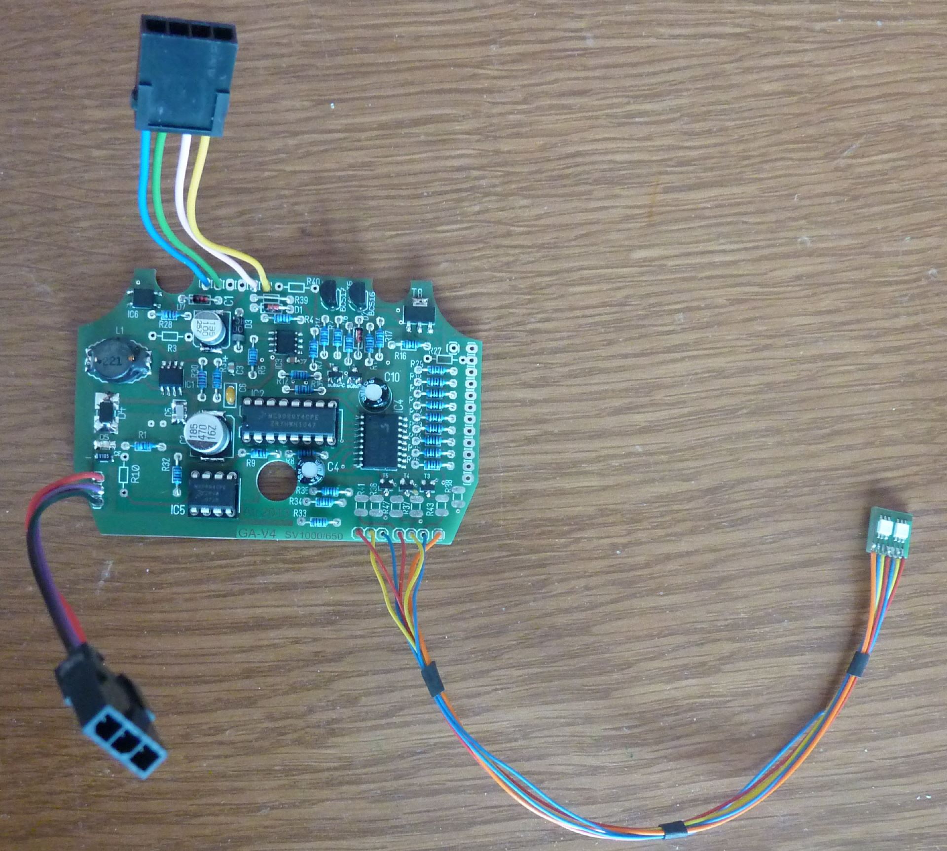
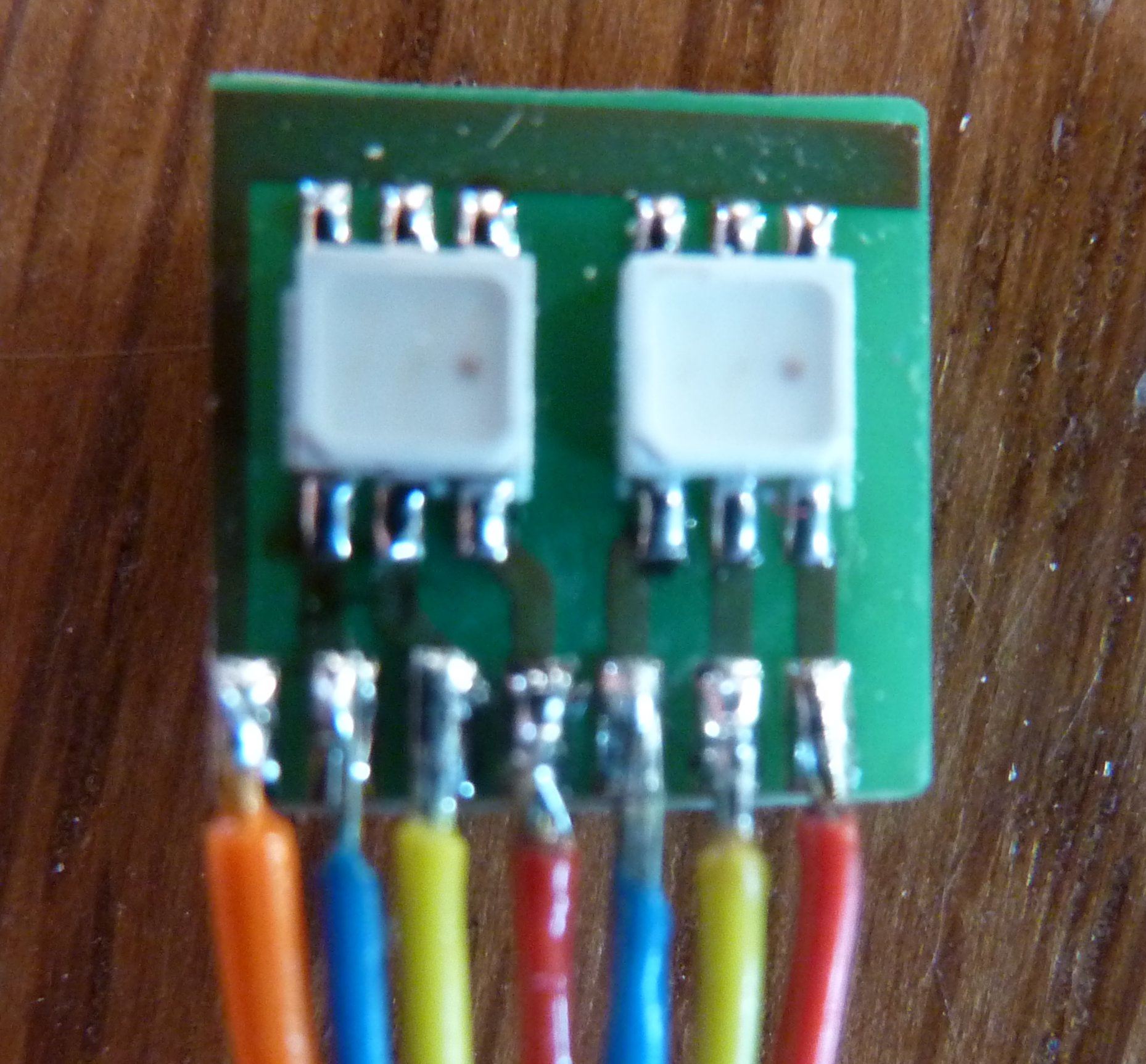
The three additional wires are introduced into the existing tube with and go through the rubber plug which seals the coupling housing to the outside, with out. The gear sensor now has two connection lines. One is the original left, while the second has been added and includes the lines of the oil thermometer.
Of course you need an appropriate evaluation for a temperature sensor. You should display relevant temperature thresholds sure. This temperature threshold in areas of the display does not quickly jumps back and forth when the temperature changes by 1 degree change, a time loop and the input side, an attenuator is built into the program. It is defined such that at least 10 seconds to be achieved, so that the display changes.
Actually, the temperature display is a simple matter. The selected sensor generates a linearly increasing with temperature voltage. The processor now has to do other to measure the voltage, and to compare these with stored threshold values. A value is always true. And depending on which value is the one corresponding to a color with Steady or Blinking is displayed.